My test with kflop, are fine and I´m going to installed in my mill,
but where do I have to conect the limit swich and Emergency Stop? Do I have
to use the driver as limit switch?
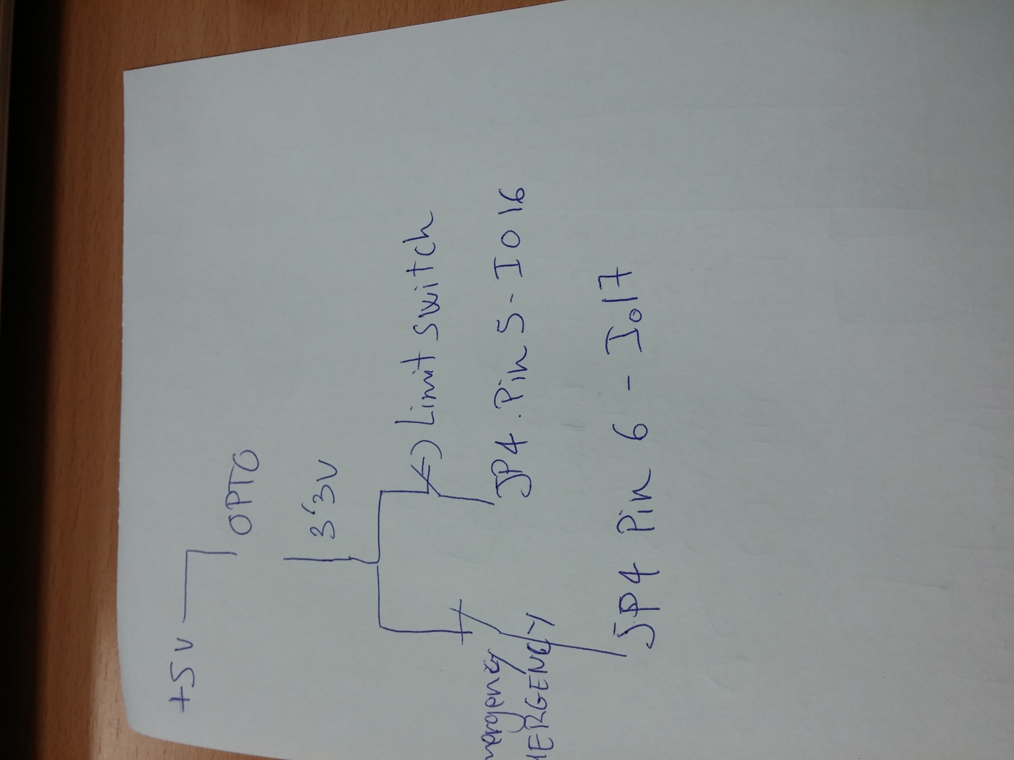
Can I use pin 5 in JP4 as input with my limit switch and pin 6 of JP4
as emergency stop? if so How I say Kflop that,
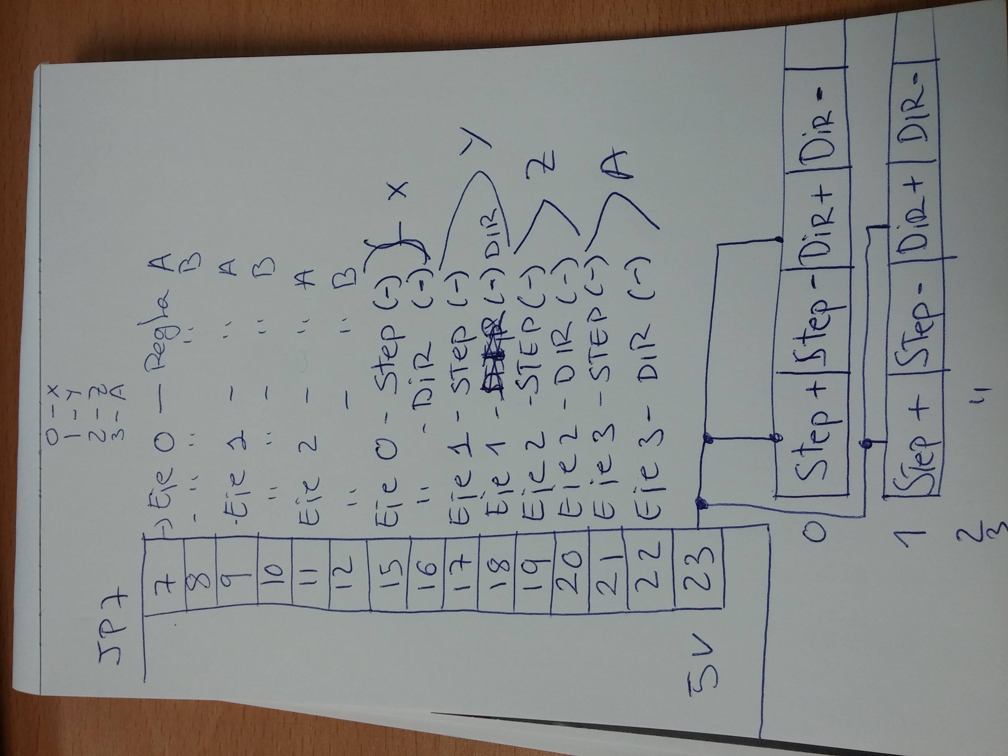
I have use pins 7,8,9,10,11,12,15,16,17,18,19,20,21,22 of JP7, I will
install scales in the 3 axis to make the close loop.
regards
El software de antivirus Avast ha analizado este correo electrónico en busca de virus.
www.avast.com
@@attachment@@
Group: DynoMotion
Message: 11858
From: Tom Kerekes
Date: 7/3/2015
Subject: Re: Kflop E-Stop [2 Attachments]
Hi Santiago,
Yes you could use pins 5 and 6 on KFLOP JP4 as 3.3V inputs. Those pins have 150ohm pull down resistors so they will go to 0V when the switches open. I don't understand why you wrote 5V + OPTO above 3.3V?? Do not connect 5V to those 3.3V pins or you will damage KFLOP.
You can configure any input bits as Limit Switch Inputs in the KFLOP Configuration.
There is no fixed EStop functionality. You can connect EStop to any input, watch it with a User Program, and perform any action you wish such as disabling KFLOP Axes.
HTH
Regards
TK
From: "'Santiago' siegc4@... [DynoMotion]" <DynoMotion@yahoogroups.com> To: DynoMotion <DynoMotion@yahoogroups.com> Sent: Friday, July 3, 2015 5:14 AM Subject: [DynoMotion] Kflop E-Stop [2 Attachments]
